|
Use of Skin-Shock at the Judge Rotenberg Educational Center (JRC) |
|
|
A Remote-Controlled Electric Shock Device for Behavior Modification
Matthew
L. Israel, Robert E. von Heyn, and Daniel A. Connolly
The Judge Rotenberg
Center
David
Marsh
Harmony Design, Inc., Harmony,
JRC pub. no. 92-3
The authors designed and used a remote-controlled, electric shock device for human behavior modification after having limited success with the Self-Injurious Behavior Inhibiting System (SIBIS). The new device, the Graduated Electronic Decelerator (GED), incorporates design changes based on the authors’ extensive experience with SIBIS. Improvements include higher intensity, adjustable duration, remote electrodes permitting more body sites for electrode placement, louder stimulation-indicator, feedback signaling of actual skin stimulation rather than simply the receipt of a transmitter signal, greater range, and rechargeable batteries. Measurements were taken of the SIBIS and GED current applied to both resistors and to skin.
Electric shock, employed as
a decelerative consequence, has proven to be one of
the most effective and most thoroughly researched behavior modification tools
(Carr & Lovaas, 1983; Favell et al., 1982; Matson & Taras, 1989). In some cases, it has proven to be a
life-saving treatment (Beck et al., 1980; Cunningham & Linscheid, 1976; Lang & Melamed, 1969; Watkins, 1972; Worsham, Israel, von Heyn,
& Connolly, 1992). Linscheid, Iwata, Ricketts,
Williams, and
In 1988, we decided to employ electric shock as part of a court-authorized treatment program for several students for whom nonaversive programming, psychotropic medication, and several aversive procedures had previously failed. At that time there were only two commercially-available shock devices designed for use with humans, WhistleStop (Farrall Instruments, Inc., P.O. Box 1037, Grand Island, Nebraska, 68802) and the Self-Injurious Behavior Inhibiting System (SIBIS) (Human Technologies, Inc., 300 3rd Avenue North, St. Petersburg, Florida, 33701). Features of SIBIS discussed in this article are those of units manufactured during 1988-90. Other electric shock devices reported in the literature were either lab-built or designed for animals.
Both the SIBIS and WhistleStop consist of a stimulator worn on the student’s body and a remote controller. Two types of remote controllers are available for the SIBIS. One is an accelerometer-activated controller worn by the student in a headband and automatically set off by a blow to the head. The other is a hand-held, button-activated controller. WhistleStop is supplied with only a hand-held controller.
We chose the SIBIS for use
at BRI because of its recent design by the Johns Hopkins Applied Physics
Laboratory in consultation with Linscheid and Iwata
(Linscheid et al., 1990), its registration with the
Food and Drug Administration as a medical device, and its use of a coded radio
signal. This coding prevents the signal from one student’s transmitter from
setting off other SIBIS stimulators in use nearby. WhistleStop’s signal is not coded.
We chose the hand-held
remote controller to activate SIBIS because the inappropriate behaviors we
planned to treat included topographies other than head-hitting and because, in
treating head-hitting, we wanted to consequate the
very earliest phase of any head-hitting behavior.
During the period
Problems with SIBIS
Intensity
Linscheid et al. (1990) reported the SIBIS’s current to be 3.5 mA, when
applied to a 24 kΩ resistor. They did not specify whether this was the peak
current or average current, as would be specified by the root mean square (rms) method. We tested a SIBIS unit purchased
in September, 1989. When set at its maximum intensity level, and applied to a 24
kΩ resistor with a fully charged battery, it produced an average
voltage of 48.6 volts (rms). Voltages were measured
with an oscilloscope (
When compared to the shocks
generated by WhistleStop and devices designed for use
with animals, SIBIS, even when set at maximum intensity and fitted with fresh
batteries, delivers a relatively mild shock. Therapists at BRI grew accustomed
to testing SIBIS each day on their own thumbs or arms to make sure that it was
in working order. Some individuals reported that they could hardly feel the
stimulation, or could not feel the stimulation at all.
One problem with using a
weak electrical stimulus in behavior modification is that it may not be strong
enough to decelerate the target behavior. Even if it does have a mildly decelerative effect, numerous applications may be required
to accomplish any significant deceleration, and this frequent use increases the
likelihood of adaptation. (Azrin,
1956; Hamilton & Standahl, 1969; Holz & Azrin, 1962; Skinner,
1938). Research with both animals and humans suggests that for maximal
effectiveness, an electrical stimulus should be as intense as possible,
consistent with safety (Azrin, 1960; Carr & Lovaas, 1983; Van Houten,
1983).
After using SIBIS for
several months, the device appeared to lose its effectiveness with several
students, a result we attributed to adaptation. We then modified our units to
produce a current of 3.4 mA (rms) when applied to a 24 kΩ resistor. In order to test the
actual current of these units when applied to skin, 10 volunteers were enlisted.
They each received a SIBIS stimulation while
measurements were taken with an oscilloscope. Overall SIBIS voltage was
measured, and at the same time the voltage was measured across a 100 Ω precision
resistor in series with the skin shock circuit. Actual current was calculated
from the latter measurement. The results of these measurements can be seen in
Table 1 under the columns with an "S" heading. Both mean and median current of
SIBIS stimulations to 10 volunteers were 4.4 mA (rms).
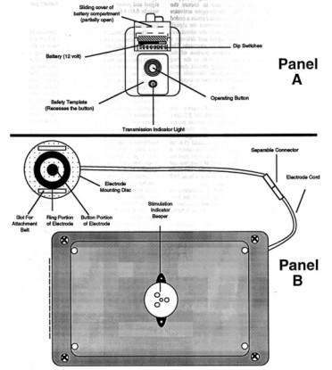
Figure
1. Diagram of GED showing transmitter in Panel A and stimulator,
electrode cord, and electrode in Panel B.
SIBIS uses one
non-rechargeable 9-volt battery. SIBIS’s receiver
board consumes a steady supply of power because it is constantly powered up,
waiting for a transmitted signal. This constantly weakens the batteries, even
without activation of the unit. Consequently, the actual intensity of any shock
depends on the condition of the battery, and this depends on how long the unit
has been in use, and on how many shocks have been delivered. When the supply
voltage from the battery drops to 8 volts, a low battery indicator beeper
sounds.
To keep the SIBIS output
reasonably constant, we changed its battery every 12 hours. This
resulted in additional expense of more than $160.00 per student per month.
Frequent changing of batteries also resulted in discontinuities in the wires
leading to the battery connector. These occurred either because they broke loose
from the solder site or the wire itself broke from the repeated movement
stress.
Duration
Duration of the SIBIS
stimulation, for the units supplied to us, was fixed at 0.2 seconds by the
manufacturer. User adjustment of duration was not possible. Clinicians using
other devices have employed durations ranging from 0.2 s to 2.0 s (Carr &
Lovaas, 1983). Research with animals has shown that
decelerative effectiveness can be enhanced by
increasing the stimulation duration (Church, Raymond, & Beauchamp,
1967).
Electrode Contact with
the Skin
Because SIBIS’s electrode is permanently attached to the housing of
the stimulator, the skin sites to which the electrode can be applied are limited
to those areas (usually arms or legs) to which the housing can be conveniently
attached.
The manufacturer supplied
us with a cotton pocket for holding the device against the skin, with a Velcro
strap which wrapped around the arm or leg. A hole in this pocket, through which
the electrode protruded, enabled the electrode to make contact with the skin.
The weight of the stimulator often caused it to shift in the pocket, misaligning
the electrode and the hole. Sometimes the entire pocket slipped down the
student’s leg or arm. We tried replacing the factory-supplied pocket with an
elastic wrap to keep the device more securely in place, but this sometimes
constricted circulation.
Indicator
Beeper
SIBIS contains an indicator
beeper which sounds when the stimulator receives a coded radio signal from its
associated transmitter; however, receipt of this signal does not necessarily
indicate that an electrical stimulation has taken place. For example, if the
electrode is not making adequate contact with the skin when the stimulator
receives the signal, the beeper sounds, but the stimulation is not actually
delivered to the student’s skin. Conversely, it is possible for an erroneous
stimulation to be delivered to the student without the beeper being activated.
For example, if some accidental equipment failure (rather than a signal
deliberately sent by the therapist) were to activate the stimulator, the student
would receive a shock, but the beeper would not sound. In such a case, the
therapist would have no way of knowing that a shock had been delivered to the
student, except by the student’s reaction.
SIBIS’s indicator beeper is situated inside
the housing of the stimulator. The housing muffles the beeper’s sound, and our
therapists sometimes could not hear the beeper over the normal sounds of the
classroom. As a result, therapists often had to move close to the student when
activating the unit to listen for the beeper. Such approaches may inadvertently
have provided potentially rewarding attention to the student immediately after
having displayed an inappropriate behavior. In such cases the aversiveness of SIBIS may have been reduced or even
overridden by the rewarding effects of this attention.
Range
A typical SIBIS unit, with
its receiver circuits properly tuned, had a range of about
6.1 m. In some
cases the range dropped to a meter or less, and its circuits required re-tuning
in order to restore normal range. Inadequate range required the therapist to
move close to the student, in order to successfully activate the stimulator.
Again, these approaches occurring immediately after inappropriate behavior may
have had unintended, potentially rewarding countertherapeutic effects.
Effectiveness
We employed SIBIS with 29
students. For two of these (7%) SIBIS was effective throughout its period of
use. For 15 students (52%) SIBIS was effective during an initial period lasting
from a few days to a few months; however, it lost its effectiveness thereafter.
With one of these students there were indications that SIBIS even reversed its
function, changing from an aversive stimulus into a positively reinforcing
stimulus. For the remaining 12 (41%) SIBIS showed little or no effectiveness at
any time. A more complete summary of our experience with SIBIS is in preparation .
GED Components and
Operation
In order to remedy the
problems described above and have ready access to repair capability and new
units, we decided to design our own remote-controlled shock device, called the
Graduated Electronic Decelerator (GED).
During the period December
1990 to August 1992, BRI manufactured 71 GEDs and used them with 53 different
students, accumulating a total of 525 student-months of experience. As of August
1992 the average (median) student had used the device for a period of 10.3
months. When employed in a student’s program, the GED, like the SIBIS, was worn
24 hours per day.
Figure 1 is a photograph of
the GED components. Shown are transmitter (A), single-output battery pack (B),
multiple-output battery pack (C), stimulator (D), electrode cord (E), and
electrode (F).
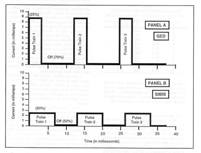
Figure
2.
Train of direct current pulses of
GED and SIBIS, when applied to a 50kΩ fixed resistor. Percentage in first pulse is duty
cycle of device. Notice that the GED has a 25% duty cycle (current on) and
75%
current off period.
When the transmitter button
is depressed, a coded radio signal is sent to the stimulator. The stimulator’s
receiver circuit decodes the signal, and sends a train of unipolar, rectangular pulses to the electrode. The current
passes through the patient’s skin from the electrode’s center button to its
outer ring. A current-level sensing circuit detects the passage of this current
through the electrode, and causes the stimulator’s stimulation-indicator beeper
to sound for the duration of the stimulation.
Transmitter and Receiver
Systems
We use an
“off the shelf” SECO-LARM RF Receiver (Model SK-910 ,
315 MHz)
TWO-CHANNEL
RF RECEIVER
This receiver incorporates:
Hi-Q SELECTIVITY and a CODING IC for rejecting unwanted
RF signals.
HIGHER SENSITIVITY for greater operating
distances.
UNSURPASSED ANTENNA MATCHING CAPABILITIES so the receiver is less
affected by where mounted.
GREATER
TUNING STABILITY so the receiver's frequency remains unaffected by shock and
vibration.
·
Frequency
315MHz.
·
2 Mode
switches (one for each channel) for easy transmitter learning.
·
Learns up to
30 transmitters (15 for each receiver channel).
·
Size:
31/4" x 33/8" x 11/8" (83 x 85 x
28mm).
The
transmitter used is also “off the shelf” from SECO-LARM (model SK-919TD2A)
TWO-CHANNEL
RF TRANSMITTER
·
Frequency 315
MHz
·
Operates up
to 500 feet (200 meters).
·
Over 68
billion possible codes.
·
Compatible
with SK-910R2,
·
Size:
21/4" x 11/4" x 1/2" (57 x 32 x 12mm).
An operating button and a
transmission indicator lamp are located on the transmitter housing. The LED
lights when the button is depressed and stays on until it
is released, indicating that the signal is being sent.
The receiver is much like
an FM radio. A code is derived from a signal comprised of high levels and low
levels. .
The GED’s stimulator will
not generate a stimulation until it has received a
signal from the transmitter for a continuous period of 0.7 s. This reduces the
chance of an unintended application due to a brief, accidental button
press.
Two types of battery pack
systems are currently being used. One is used for the GED and one for the
GED-4
The GED battery pack
provides power to its associated stimulator at all times. This pack contains a
12 -volt rechargeable
NiCd battery at 1600 ma (Panasonic P/N N124) enclosed in a plastic housing The
GED-4 battery pack consists of twin NiCd Panasonic battery packs, P/N
N124
Stimulator
(GED)
The stimulator weighs 0.31
kg and consists of a plastic housing (14.6 cm x 9.1 cm x 3.3 cm), , a
receiver/decoding circuit board set to the same code as the transmitter , a
shock controller circuit board, an electrode connected to the stimulator by a
cord, and a stimulation-indicator beeper. When the stimulator’s
receiver/decoding circuit board receives a properly coded signal, the shock
controller circuit generates a train of unipolar
pulses through the electrode which activates the stimulation-indicator beeper
for the duration of the pulse train, and the LED remains on for two
minutes.
The electrode cord is made
from flat 6-conductor telephone cable (Hirose Electric Co., Ltd., Part #
H0063-ND) and connects to the stimulator by a modular connector (6-position
offset latch, AMP Model #555237-3).
Two types of electrode are
currently being used. The first is a "concentric ring" type, similar to that
used by the SIBIS and described by Tursky (1965). It
consists of a stainless steel button (diameter 9.5 mm, thickness 3.25 mm) inside
a stainless steel ring (outer diameter 21.5 mm, inner diameter 16.5 mm,
thickness 3.25 mm), with 2.35 mm between the outer edge of the button and the
inner edge of the ring. The button and ring are mounted on a plastic electrode
mounting disc (60 mm x 19 mm) and protrude 4.0 mm above its top surface. The
second consists of two stainless steel buttons (diameter 9.5 mm, thickness 3.25
mm) separated by a varying distance of up to six inches and mounted on flexible
nonconductive material.
The stimulation-indicator
beeper is a Mallory piezoelectric ceramic buzzer (PLD-27A 35W), rated at 95 dB.
It is mounted inside the GED’s housing
and is loud enough to be heard in a noisy classroom.
Attachment of Stimulator
and Electrode to Student
The student wears a
modified "belt pack" (a zippered pouch worn around the waist) which holds the
battery pack and stimulator. The electrode cord exits from a small hole in the
back of the belt pack. The electrode cord and electrode are normally covered by
the student’s clothing.
If the electrode is
attached to an arm or leg, a limb belt made of a cotton elastic blend is
threaded through the two slots in the electrode mounting disc and secured around
the arm with a suspender buckle. The electrode can also be attached to the torso
using a longer belt. Other equipment has been designed to
attach the electrode to the fingers or to the bottom of the foot. These
attachment methods eliminate the need for elastic wraps or adhesive bandages to
secure the electrode against the skin, enable a maximum amount of air to reach
the skin near the electrode, and allow the electrode to be placed at a wide
variety of body sites.
Parameters of GED
Stimulation
In choosing parameters for
the GED’s electrical stimulation, our goal was to maximize decelerative effectiveness while minimizing any possible
adverse effects on the skin. Wherever the shock literature did not contain
information concerning decelerative effectiveness,
parameters were chosen to maximize perceived aversiveness, as determined by tests on volunteer members of
the BRI/JRC staff. All parameters except the waveform’s rectangular shape can be
changed by technicians.
Waveform. Each GED
stimulation
consists of a train of rectangular-wave unipolar
pulses. A portion of a GED pulse train is depicted in Panel A of Figure 2. A portion of a SIBIS waveform is shown in
Panel B of Figure 2 for comparison.
- - - - - - - - - - - - - -
- - -
Insert Fig. 2 about
here
- - - - - - - - - - - - - -
- - -
Duty
cycle.
Duty cycle is the
percentage of time that a pulse is on during a single on-off cycle. For example,
as shown in Figure 2, Panel A, the GED pulse is on for 25% of each cycle.
Current is on for 3.125 ms, and off for 9.375 ms. The
total time for one cycle is 12.5 ms.
During the design of GED,
eight volunteers tested the perceived aversiveness of
the stimulation at 10%, 25%, and 50% duty cycles. They reported little
perception of aversiveness at a 10% duty cycle, and
definite aversiveness at 25%. They found the 50% duty
cycle only slightly more aversive than the 25% duty cycle. Because the 50% duty
cycle was thought more likely to cause skin irritation and was judged to be only
slightly more aversive than the 25% duty cycle, we
decided upon a 25% duty cycle for the GED. The duty cycle may be adjusted from
1% to 90%.
Current. When operated across a 24 kΩ
resistor, the GED produces a voltage of 106.3 V (rms),
and a current of 4.42 mA (rms). The corresponding peak values are 272 V and 11.33
mA.
In order to find out the
level of current during actual stimulations, tests were conducted on 10 BRI
staff members, who volunteered to participate. Each volunteer received one
200 ms application of GED to the forearm. Previous testing at BRI had shown
that peak current was reached within the first 200 ms of a
stimulation to the skin. The same measurements were taken as described
earlier for actual SIBIS stimulations. Table 2 shows the results under the
columns headed "G.". The median peak current for the volunteers was 29.2 mA (range 12.8 mA to 39.6 mA), and the mean was 29.6 mA.
Median and mean rms currents were 14.6 mA and 14.8 mA, respectively. The
median impedance for the 10 volunteers was 4.0 kΩ (range 3.1 kΩ to 13.4 kΩ); the
mean was 5.0 kΩ.
The maximum peak
current possible from GED, measured by applying GED to a 100 Ω resistor, was 56
mA. This level of current would not be generated when
the device is applied to the skin, however, because skin has a typical impedance
of two to five kΩ.
Pulse repetition
frequency. Pulse
repetition frequency refers to the rate, in pulses per second (pps), at which pulses occur within a pulse train. Informal
tests on a few volunteers during GED’s design phase suggested that perceived
aversiveness decreases rapidly when the pulse
repetition frequency is below 40 pps or above 120
pps. GED was given a pulse repetition frequency of 80
pps. (80 Hz) This setting may be adjusted by a
technician to any value between 40 and 120 pps.
Duration. The duration of a single GED
stimulation is completely adjustable. We have selected a
duration of 2.0 seconds for the typical
application.
For our test purposes, we
use a 5 k Ω. load (5000 ohms), which most closely
simulates average skin resistance.
This produces 65 vrms output with a median
current of 13 mA for the GED and a 130 vrms output with a median current of 26 mA for the GED-4
Safety
Issues
GED’s stimulation-indicator
generates a tone only if current passes through the skin between the stimulator
electrodes. Consequently, it reliably alerts staff to any accidental firings. In
addition a dual timer prevents the duration from exceeding a preset level, and
intensity is limited by a voltage limiting varistor
and a current limiting resistor.
During the GED’s
development several BRI staff members volunteered to receive stimulations to
evaluate possible adverse side effects to the skin. One side effect noted in a
few cases was a browning of the skin immediately under the electrode. This
occurred whether the device was operated or not, and appeared to be a chemical
effect resulting from the interaction of the metallic electrode with the skin.
It tended not to occur when electrodes had been used for some time.
A second effect, which has
been noted at some time in about one third of our students, has been slight
erythema and, in a few cases, a skin blister. We have
found that these effects can be avoided by altering the location of the
electrodes or by adjusting the duration or voltage of the device.
Two consulting
cardiologists, two neurologists, a psychiatrist, and a pediatrician, all of whom
have examined students who have received many applications of the GED, have
expressed the opinion that the GED’s stimulation parameters are within safe
levels. Although there is no danger of cardiac stimulation from the GED, even if
applied directly to the chest over the heart, we have made it a practice not to
place the electrodes over the heart area.
References
Azrin, N. H. (1956). Effects of two intermittent schedules of immediate and nonimmediate punishment. Journal of Psychology, 42, 3–21.
Azrin, N. H. (1960). Effects of punishment intensity during variable-interval reinforcement. Journal of the Experimental Analysis of Behavior, 3, 123–142.
Beck, G. R., Sulzbacher, S. I., Kawabori, I., Stevenson, J. G., Guntherof W. G., and Spelman, F. A. (1980). Conditioned avoidance of hypoxemia in an infant with central hypoventilation. Behavior Research of Severe Developmental Disabilities, 1, 21–29.
Butterfield, W. H. (1975). Electric shock hazards in aversive conditioning of humans. Behavioral Engineering, 3, 1–28.
Carr, E. G. and Lovaas, O. I. (1983). Contingent shock treatment for behavior problems. In S. Axelrod & J. Apsche (Eds.), The effects of punishment on human behavior. (pp. 221–245). New York: Academic Press.
Church, R. M., Raymond, G. A., and Beauchamp, R. D. (1967). Response suppression as a function of intensity and duration of a punishment. Journal of Comparative and Physiological Psychology, 63, 39–44.
Cunningham, C. E. & Linscheid, T. R. (1976). Elimination of chronic infant ruminating by electric shock. Behavior Therapy, 7, 231–234.
Favell, J. E., Azrin, N. H., Baumeister, A. A., Carr, E. G., Dorsey, M. F., Forehand, R., Foxx, R. M., Lovaas, O. I., Rincover, A., Risley, T. R., Romanczyk, R. G., Russo, D. C., Schroeder, S. R., and Solnick, J. V. (1982). The treatment of self-injurious behavior. Behavior Therapy, 13, 529–554.
Hamilton, J. & Standahl, J. (1969). Suppression of stereotyped screaming behavior in a profoundly retarded institutionalized female. Journal of Experimental Child Psychology, 7, 114–121.
Holz, W. C., and Azrin, N. H. (1962). Recovery during punishment by intense noise. Psychological Reports, 11, 655–657.
Lang, P. J. and Melamed, B. G. (1969). Avoidance conditioning therapy of an infant with chronic ruminative behavior. Journal of Abnormal Psychology, 74, 1–8.
Linscheid, T. R., Iwata, B. A., Ricketts, R. W., Williams, D. E. & Griffin, J. C. (1990). Clinical evaluation of the self-injurious behavior inhibiting system (SIBIS). Journal of Applied Behavior Analysis, 23, 53–78.
Matson, J. L. & Taras, M. E. (1989) A 20-year review of punishment. Research in Developmental Disabilities, 10, 85–104.
Skinner, B. F. (1938). The behavior of organisms. New York: Appleton.
Tursky, B., Watson, P. D., and O’Connell, D. N. (1965). A concentric ring electrode for pain stimulation. Psychophysiology, 1, 296–298.
Van Houten, R. (1983). Punishment: From the animal laboratory to the applied setting. In S. Axelrod & J. Apsche (Eds.), The effects of punishment on human behavior. (pp. 13–44). New York: Academic Press.
Worsham, R. W., Israel, M .L., von Heyn, R. E., and Connolly, D. A. (1992). Treatment of life-threatening vomiting and rumination with contingent electric shock. Unpublished manuscript.
Watkins, J. T. (1972). Treatment of chronic vomiting and extreme emaciation by an aversive stimulus: case study. Psychological Reports, 31, 803–805.
Author Notes
Matthew L. Israel conceived of the GED and prepared the final manuscript. Robert von Heyn designed and supervised the parametric testing and assisted in the manuscript preparation and editing. Dan Connolly assisted in the parametric research and the manuscript preparation and editing. David Marsh designed the GED.
The authors gratefully acknowledge the technical contributions of Chris Mello, Richard Levinson, Vandy Sou, Dan Hey, and Karl Weisker in the design of GED, and Thomas Kearney for his exhaustive researching of the shock literature. In addition, the comments of Bob Worsham on the manuscript, and the advice of Drs. Paul E. Zoll and Tadeusz Gotlib concerning the safety of GED, were invaluable.